
Page 152 - RESIDEO - HONEYWELL HOME - LISTINO 2024
P. 152
7.02 - FILTRI AD “Y” Braukmann
Filtri ad “Y” flangiati per applicazioni industriali
FY69P
Filtri ad “Y” flangiati PN16
• Corpo in ghisa
• Magliatura da 0,5 mm
• Per acqua, olio e aria compressa
• Tmax 85 °C - Pmax 16 bar
Modello Descrizione Euro Imballo
FY69P-50A
DN = 50 alve
D15S Pressure Reducing V - Kvs 61,0 207,00 1
FY69P-65A DN = 65 - Kvs 107,0 297,00 1
FY69P-80A
DN = 80
Method of Operation - Kvs 151,0 346,00 1
455,00
1
- Kvs 190,0
FY69P-100A
DN = 100
Spring loaded pressure reducing valves operate by means of a The inlet pressure has no influence in either opening or closing of
FY69P-125A
force equalizing system. The force of a diaphragm operates the valve. Because of this, inlet pressure fluctuation does not
DN = 125
- Kvs 297,0
1
791,00
against the force of an adjustment spring. If the outlet pressure influence the outlet pressure, thus providing inlet pressure 1
1.128,00
FY69P-150A
DN = 150
-Kvs 378,0
and therefore diaphragm force fall because water is drawn, the balancing.
DN = 200
- Kvs 700,0
FY69P-200A
then greater force of the spring causes the valve to open. The 2.270,00 1
outlet pressure then increases until the forces between the
diaphragm and the spring are equal again.
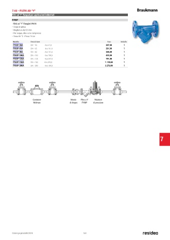
Installation Example
Contatore Valvola Filtro a Y Riduttore
4
1
3
Woltman di ritegno 2 FY69P di pressione 5
Figure 1: Installation example
1 Shut-off device
2 Check valve
3 Strainer
4 Pressure reducing valve
5 Shut-off valve
Connection size DN 65 80 100 150 200
Inch 2 1/2“ 3“ 4“ 6“ 8“
W 1 mm 120 130 145 200 230 7
1. Minimum distance from wall to centre line of pipework
Installation Guidelines Typical Applications
• Install in horizontal pipework with spring bonnet directed Pressure reducing valves of this type are suitable for multi
upwards dwelling buildings, industrial and commercial applications within
• Install shut-off valves the range of their specifications.
• The installation location should be protected against frost The pressure reducing valve should be installed, if one or more
and be easily accessible: of the following conditions apply:
- Pressure gauge can be read off easily
- Simplified maintenance and cleaning • The static pressure exceeds the maximum permissible value
• Install downstream of the filter or strainer. This position for the system.
ensures optimum protection for the pressure reducing valve • Several pressure zones are required when a pressurisation
system is used (pressure reducers on each storey of a
against dirt.
• Provide a straight section of pipework of at least five times the building).
nominal valve size after the pressure reducing valve (in • Pressure fluctuations in the downstream system must be
accordance with DIN EN806 part 2) avoided.
• To achieve constant inlet and outlet pressures on pumped
pressure boosting systems.
• To reduce the water consumption.
2 http://ecc.emea.honeywell.com EN0H-1049GE23 R0815 • Subject to change
150 Catalogo prodotti 2024 151
151
150