
Page 77 - OLI - OLIFLEX
P. 77
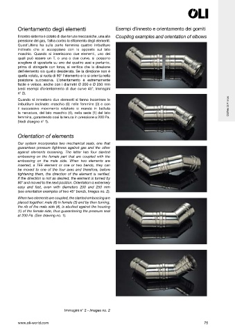
Orientamento degli elementi                       Esempi d’innesto e orientamento dei gomiti

          Il nostro sistema è dotato di due tenute meccaniche, una alla  Coupling examples and orientation of elbows
          pressione dei gas, l’altra contro lo s lamento degli elementi.
          Quest’ultima  ha sulla parte  femmina quattro imbutiture
          inclinate che si accoppiano con le opposte sul lato
          maschio. Quando si inseriscono due elementi, uno dei
          quali può essere un T, o una o due curve, si possono
          scegliere di spostarle su uno dei quattro assi e pertanto,
          prima di stringerle con forza, si veri ca che la direzione
          dell’elemento sia quella desiderata. Se la direzione non è
          quella voluta, si ruota di 90° l’elemento e lo si orienta nella
          posizione successiva. L’orientamento è estremamente
          facile e veloce, anche con i diametri Ø 200 e Ø 250 mm
          (vedi esempi d’orientamento di due curve 45°, Immagini
          n° 2).
          Quando si innestano due elementi si fanno incontrare le
          imbutiture inclinate: maschio (6) nelle femmine (3) e con
          il successivo movimento rotatorio si manda in battuta                                                      OLI ex S.P. inox
          la nervatura, del lato maschio (4), nella sede (1) del lato
          femmina, garantendo così la tenuta in pressione a 200 Pa.
          (Vedi disegno n° 1).


          Orientation of elements
          Our  system  incorporates  two  mechanical  seals,  one  that
          guarantees  pressure  tightness  against gas  and  the  other
          against  elements  loosening.  The  latter  has  four  slanted
          embossing on the female part that are coupled with the
          embossing on the male side. When two elements are
          inserted, a TEE element or one or two bends, they can
          be moved to one of the four axes and therefore, before
          tightening them, the direction of the element is verified.
          If the direction is not as desired, the element is turned by
          90° and moved to the next position. Orientation is extremely
          easy and fast, even with diameters 200 and 250 mm
          (see orientation examples of two 45° bends, Images no. 2).
          When two elements are coupled, the slanted embossing are
          placed together: male (6) in female (3) and by then turning,
          the rib of the male side (4), is abutted against the housing
          (1) of the female side, thus guaranteeing the pressure seal
          at 200 Pa. (See drawing no. 1).


                                  Immagini n° 2 - Images no. 2


          www.oli-world.com                                                                             75